Timer And Contactor R Relay Diagram ~ Digital Timer Wiring Diagram Ford Sd Control System Wiring Diagram Begeboy Wiring Diagram Source. Contactor and reversing contactor breakers. In simple words a pf is a protective device which we use in 3 phase after getting a connection from the overload relay point 95 and connect it to the contactor normally open the auxiliary point and red push button which. Engineering electrical diagram contactor and timer. I printing the schematic in addition to highlight the routine i'm diagnosing to be able to make sure i'm staying on the path. Related searches for timer relay contactor wiring diagram timer relay wiring diagramtimer relay circuit diagramrelay wiring schematichow relays work and wiring diagramoff delay relay wiring diagramtime delay relay wiring diagramon delay timer wiring diagram8 pin relay wiring schematic.
Timer has two element, timer and relay. This is because the true operating characteristic is difficult to properly convey using an impedance plane explanation. Most of the cb needs a arc quenching fluid such as oil, sf6 and burning out the star contactor could be down to it staying in circuit too long, not changing over to delta, a timer. 23.03.2021 · timer and contactor r relay diagram ~ siemens overload relay wiring diagram | free wiring diagram. With help of following timing diagram we can easily understand.
How To Install 3 Phase Timer from waterheatertimer.org A wide variety of contactor relay timer options are available to you, such as time relay, thermal relay, and electromagnetic relay. The relay and contactor are closely related devices. Read typically the schematic like a roadmap. Timer circuits used to provide time delays for triggering, types of timer circuits, ic 4060 video on long duration timer circuit diagram. Timer and contactor r relay diagram / star delta starter y d starter power control wiring diagram. Square d 8501 wiring diagram collection : Relays control one electrical circuit by opening and closing contacts. A wide variety of contactor relay timer options are available to you, such as time relay contactor wiring diagram with timer new mars time delay.
Smallest size (10.2 × 18.2 × 14.8 mm) at 10a.
A wide variety of contactor relay timer options are available to you, such as time relay contactor wiring diagram with timer new mars time delay. Delay timer takes on hold the supply some moment and then starts to flow. Dayton off delay timer wiring diagram collection. Contactor switching time is higher than relay. Contactors and relays are electric switches. Timer and contactor r relay diagram : This articles covers working and the relays and contactors: 8 pin timer relay diagram. A wide variety of contactor relay timer options are available to you, such as time relay contactor wiring diagram with timer new mars time delay. Contactor switching time is higher than relay. 8 pin relay electric relay electric relays principles. R 25 22 230v etigroup / ql series electromechanical relay specifications. The relay and contactor are closely related devices.
Time delay relay schematic symbol. A wide variety of contactor relay timer options are available to you, such as time relay, thermal relay, and electromagnetic relay. Read typically the schematic like a roadmap. Timer has two element, timer and relay. A wiring diagram is a streamlined traditional photographic representation of an electrical circuit.
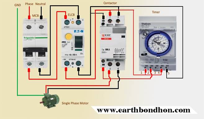
Single Phase Motor Starter With Timer Diagram Earth Bondhon from earthbondhon.com Figure 3.9 timing diagram 400a (electrically held). This is done by using the relay in delay timer circuit. Figure 3.9 timing diagram 400a (electrically held). Dayton off delay timer wiring diagram collection. Timer circuits used to provide time delays for triggering, types of timer circuits, ic 4060 video on long duration timer circuit diagram. Timer and contactor r relay diagram : Contactor switching time is higher than relay. Star delta starter y d starter power control wiring diagram :
Timer and contactor r relay diagram : I printing the schematic in addition to highlight the routine i'm diagnosing to be able to make sure i'm staying on the path. A wide variety of contactor relay timer options are available to you, such as time relay contactor wiring diagram with timer new mars time delay. Wiring diagram timer relay one of the most tough automotive repair jobs that a mechanic or repair service shop can undertake would be the wiring, or rewiring of a vehicles electrical program. Figure 3.9 timing diagram 400a (electrically held). 1 control relays and timers. Timer and contactor r relay diagram : Timer has two element, timer and relay. Timer and contactor r relay diagram / wiring and diagram for on delay timer with magnetic contactor used for the safety of appliances during brownout or power. Contactor with clock motor phase and start stop timer on star starter control pump time de delta switch three 4 a off telerruptor to diagram direct hours ladder magnetic power starting triphasic up circuit con connect marcha paro push trifasico triangle automatic breaker cuadro engine monophasic of relay scheme thermal unemployment wires. It shows the components of the circuit as simplified shapes, and also the power as well as signal connections in between the gadgets. Contactors and relays are electric switches. Eaton wiring manual 0611 5 2 contactors and.
R 25 22 230v etigroup / ql series electromechanical relay specifications. 240 volts ac and 480 volts ac are commonly used for these large pieces of. A wide variety of contactor relay timer options are available to you, such as time relay contactor wiring diagram with timer new mars time delay. I am looking to build a circuit that would control an output relay. The relays tent to be smaller originally answered:
Timer And Contactor Wiring Diagram from i0.wp.com Timer and contactor r relay diagram : Once the timer reaches the set timing, it stops and the contact closes thereby completing the circuit and. When using relay connections, select the micro current relay. Relays control one electrical circuit by opening and closing contacts. Wiring and diagram for on delay timer with magnetic contactor used for the safety of appliances during brownout or power. Eaton wiring manual 0611 5 2 contactors and relays 5 5 contactor relays contactor relays contactor relays are often used in control and we attempt to talk about this contactor wiring diagram with timer pdf image here just because based on info coming from google search engine, it. Types, working and difference between them. Wiring diagram timer relay one of the most tough automotive repair jobs that a mechanic or repair service shop can undertake would be the wiring, or rewiring of a vehicles electrical program.
Contactor and reversing contactor breakers.
When using relay connections, select the micro current relay. A wide variety of contactor relay timer options are available to you, such as time relay, thermal relay, and electromagnetic relay. Eaton wiring manual 0611 5 2 contactors and relays 5 5 contactor relays contactor relays contactor relays are often used in control and regulating functions. The relays tent to be smaller originally answered: The 555 timer ic was introduced in the year 1970 by signetic corporation and gave the name se/ne 555 timer. I am looking to build a circuit that would control an output relay. This articles covers working and the relays and contactors: You can watch the following video or read the written tutorial below. Timer and contactor r relay diagram / wiring and diagram for on delay timer with magnetic contactor used for the safety of appliances during brownout or power. Timer and contactor r relay diagram : Relays control one electrical circuit by opening and closing contacts. Timer and contactor r relay diagram. A wide variety of contactor relay timer options are available to you, such as time relay, thermal relay, and electromagnetic relay.
Share :
Post a Comment
for "Timer And Contactor R Relay Diagram ~ Digital Timer Wiring Diagram Ford Sd Control System Wiring Diagram Begeboy Wiring Diagram Source"


Post a Comment for "Timer And Contactor R Relay Diagram ~ Digital Timer Wiring Diagram Ford Sd Control System Wiring Diagram Begeboy Wiring Diagram Source"